DPSV5 is designed to be the most suitable and ultimate power redundancy system for backup powering without batteries via coax or power cable. Using a power booster system can overcome even a 30V voltage drop over cable while maintaining the original voltage level at the remote active devices. Our simple DPSV5 configuration with a built-in power inserter makes the installation quick and easy, allowing almost no room for error when installing the system. After installation, operation is completely automatic. Full electronic protection against short circuits and overloads is standard for all our T-former power suppliespreventing any possible failure when using the DPSV5 system.
Recommendations:
1) Make sure that the DPSV5 Backup In/Out output port is connected to the main trunk or power cable, and the local output port is connected to the supported area.
2) To prevent any possibility of higher current passing through the local input port, it is recommended to connect the second port of the T-former to the PS-2 Backup power supply. In this way, the current that supports the remote area will pass via the Port-2 port while maintaining the current at the PS-1 ports.
3) The DPSV5 has left and right units to help technicians install two compatible units next to each other. This configuration enables double safety protection for synchronization circuits to insure 100% protection against short circuits. Maintaining a right and left configuration preserves the system’s original performance and provides 100% reliability.
4) After installation, turn off one of the power supplies that will operate the DPSV5 backup.
Check the voltage at the amplifier closest to DPSV5. If using a Power Booster, the voltage should always be between 60 and 66V rms (60V networks), or 80-90V (87V networks)
After testing the active power supply, repeat the test with the second power supply.
5) You can easily connect a monitoring system to Monitoring port located on the front panel of the DPS. With the newer DPS models, there are seven analog outputs that can be connected to any common monitoring system or the handy Monitoring Box supplied by Safecom. Using the new Monitoring Box supplied by Safecom, enables a technician to measure the online current and voltage from the DPS without using an external monitoring system.
Operational & Testing Instructions for the DPS system
A. Turn ON the first Power Supply. (Usually the DPS-Right unit) DPS Local & Backup power LED's should be GREEN when the first non-standby power supply is started. (Usually the first one is the "Right" Master DPS).
B. Turn ON second Power Supply. (Usually the DPS-Left unit) DPS Local Power LED should be GREEN and back-up power LED should be RED when the second non-standby power supply is started. (Usually the second one is the "Left" Slave DPS).
C. Disconnect mains power source to Power Supply on "Master" DPS; LED's will turn RED. The Fiber node or the trunk amplifier will receive alternative power from the neighboring node via the DPS. On the neighboring DPS Both LED's will be GREEN.
D. Re-establish main power source for the shutdown power supply (to the right side power supply).
E. The Master "Right" DPS: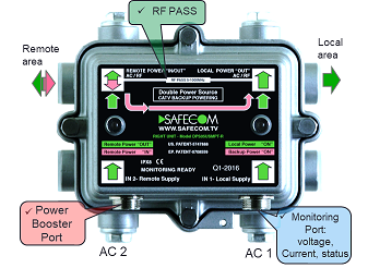
Local Power LED= GREEN.
Backup Power LED =GREEN.
The Slave "Left" DPS:
Local Power LED = GREEN.
Backup Power LED = RED.
F. Disconnect mains power source to the Power Supply in the other location. (Left side power supply). Both LED's will turn RED. (Now the fiber node or the trunk amplifier will receive alternative power from the neighbouring node (or trunk Amp) via the DPS)
G. Re-establish mains power source to the shutdown power supplies. (Left side power supply). Local Power LED = GREEN Backup Power LED = RED.
Our support team is always ready to answer any questions or support your installation.